Bar Bending Schedule for footings :-
Bar Bending schedule plays a vital role in the construction of High rise buildings. It is very important to learn Bar Bending Schedule for finding out the quantities of Steel reinforcement required for every component of the building.
For Suppose, consider the case of high rise buildings, It requires tons of steel to complete 10+ floor building. It’s impossible to order all the steel required for whole construction at a time it creates a problem of space and also steel is prone to corrosion by the contact of water (rain). To avoid this, high rise building orders reinforcement (steel) as per requirement. Firstly they find the Estimation of Steel reinforcement in footings (steel quantities) [Bar Bending Schedule for footings], required for the construction of footings. After the completion of footings they go for next order and so on.
If you are new to Bar Bending Schedule, Refer the Basics of Bar Bending schedule
if you wanted to know different types of footings check here Different types of footings
Contents
- Bar Bending Schedule for footings :-
- Quantity of Reinforcement (Steel) required for footings / Bar Bending Schedule for footings:-
- Steps involved in calculating the bar bending schedule of a footings:-
- Plain footing Bar Bending schedule:
- Isolated footings Bar Bending Schedule :-
- Stepped footings Bar Bending Schedule:
- Eccentric/Shoe footings Bar Bending Schedule:-
- Combined Footing Bar Bending Schedule:-
Quantity of Reinforcement (Steel) required for footings / Bar Bending Schedule for footings:-
The procedure to finding out the quantities of steel required for the footings, We are considering the below footing plan.
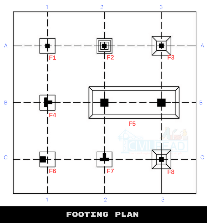
Observations from the above fig:
- F1, F4, F7 is Plain footing (1.0×1.0×0.8)
- F2 is Stepped Footing (0.9×0.9×1.35)
- F3, F8 is Isolated footing (0.9×0.9×0.5)
- F5 is Combined Isolated footing (4.2×1.7×0.9)
- F6 is Shoe footing (0.6×0.6×0.4)
True dimensions and shapes of the footings are decided and designed by the structural engineer based on soil history, type of construction, the total expected load of the structure. All the dimensions of the above columns considered only for explanation purpose.
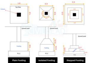
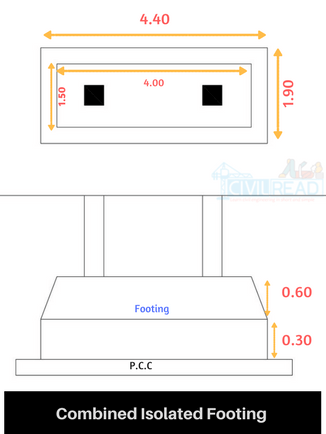
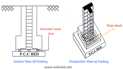
We use different types of mesh (reinforcement) in footings as per design. You can refer different types of Reinforcement used in footings from here.
Steps involved in calculating the bar bending schedule of a footings:-
Remember, Steel required for construction is ordered in Kgs or Number of Bars. The standard size of each bar is 12m. The final output of BBS calculation is in Kgs or in Number of “12m” Bars.
To make it easier calculation is divided into two parts, X bar Calculations and Y bar calculations.
X Bars are Horizontal bars in X direction and Y Bars are vertical one projected in Y Direction.
- Deduct the concrete cover to find the dimensions of bars.
- Find the Length of single X Bars & Y Bars
- Find the total length of X bars. & Y bars
- Calculate the weight of steel required per 1m
- Calculate the total number of 12m bars required
- Find the total weight of steel required.
Plain footing Bar Bending schedule:
For the calculation of the total quantity of steel required for the Plain footing, we are adopting these dimensions for bars.
Adopted:-
- Dimensions of Footing are 1.0 × 1.0 × 0.9 (Length × Breadth × Depth)
- Plain mesh is adopted for F1, F4, F7 footings
- Dia of X Bars is 16mm (Dia 16mm @ 100mm C/C)
- Dia of Y Bars is 12mm (Dia 12mm @ 100mm C/C)
- which means Center to center spacing between X bars & Y bars is 100mm
Remember, Proper Concrete cover should be adopted for the reinforcement in Footings to resist it from corrosion.
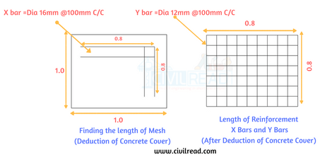
Concrete Cover deduction:
As per condition, concrete cover of 0.1m is deducted from all sides of mesh. True dimensions post deducting is 0.8×0.8 (length and breadth)
Refer below image for more details:
| Length of Each X bar | = 0.8m |
| Length of Each Y bar | = 0.8m |
| No. of X bars | [(Y Bar Length)/Spacing]+1 = [0.8/0.1]+1 = 9bars |
| No. of Y bars | [(X Bar Length)/Spacing]+1 = [0.8/0.1]+1 = 9bars |
| Total Length of X bars | = Length of each X bar × No. of X Bars = 0.8 × 9 =7.2m |
| Total Length of Y bars | = Length of each Y bar × No. of Y Bars = 0.8 × 9 =7.2m |
| Total No. of ’12m’ X bars | = 7.2/12 = 0.6bars |
| Total No. of ’12m’ Y bars | = 7.2/12 = 0.6bars |
| Weight of steel required for 1m of 16mm bar | = D2/162 = 162/162 = 1.58kg/m |
| Total weight of steel required for X bars | = 1.58 × 7.2 = 11.37Kgs |
| Weight of steel required for 1m of 12mm bar | = D2/162 = 122/162 = 0.88kg/m |
| Total weight of steel required for Y bars | = 0.88 × 7.2 = 6.33Kgs |
Total Weight of Plain Mesh
= Weight of steel required for X bars + Weight of steel required for Y bars
= 11.37Kgs+6.33Kgs =17.70Kgs
Isolated footings Bar Bending Schedule :-
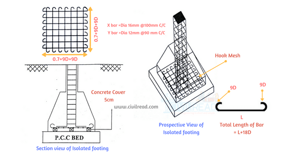
For the calculation of the total quantity of steel required for the Isolated footing, we are adopting below dimensions for bars.
Adopted:-
- Hook mesh is adopted for F3,F8 footings
- Dimensions of Footing are 0.9×0.9×0.5 (Length × Breadth × Depth)
- Dia of X Bars is 16mm (Dia 16mm @ 100mm C/C)
- Dia of Y Bars is 12mm (Dia 12mm @ 90mm C/C)
- which means Center to center spacing between X bars is 100mm & Y bars is 90mm
Remember Proper Concrete cover should be adopted for the reinforcement in Footings to resist it from corrosion.
Concrete Cover deduction:
As per condition, concrete cover of 0.1m is deducted from all sides of mesh. In hook mesh, hook is provided at the end of each bar. Each bar has two ends and therefore, hook length is included in the calculation of length of bar
Hook Length = 9d (d is the dia of bar)
Total Hooks for each bar = 2
True dimensions post deducting concrete cover is length = (0.7m+2x9d) & breadth = (0.7m+2x9d)
Refer below image for more details

| Length of Each X bar | = 0.7+2×9d d = 16mm = 0.016m = 0.7+2×9×0.016 = 0.988m |
| Length of Each Y bar | = 0.7+2×9d d = 12mm = 0.012m = 0.7+2×9×0.012 = 0.916m |
| No. of X bars | [(Y Bar Length)/Spacing]+1 = [0.7/0.1]+1 = 8bars (Don’t include hook length in calculating no. of bars) |
| No. of Y bars | [(X Bar Length)/Spacing]+1 = [0.7/0.09]+1 = 9bars |
| Total Length of X bars | = Length of each X bar × No. of X Bars = 0.988 × 8 =7.9m |
| Total Length of Y bars | = Length of each Y bar × No. of Y Bars = 0.916 × 9 =8.24m |
| Total No. of ’12m’ X bars | = 7.9/12 = 0.65bars |
| Total No. of ’12m’ Y bars | = 8.24/12 = 0.68bars |
| Weight of steel required for 1m of 16mm bar | = D2/162 = 162/162 = 1.58kg/m |
| Total weight of steel required for X bars | = 1.58 × 7.9 = 12.48Kgs |
| Weight of steel required for 1m of 12mm bar | = D2/162 = 122/162 = 0.88kg/m |
| Total weight of steel required for Y bars | = 0.88 × 8.24 = 7.25Kgs |
Total Weight of Hook Mesh
= Weight of steel required for X bars + Weight of steel required for Y bars
= 12.48Kgs+7.25Kgs =19.73Kgs
Stepped footings Bar Bending Schedule:
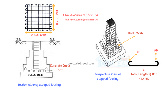
For the calculation of the total quantity of steel required for the Plain footing, we are adopting these dimensions for bars.
Adopted:-
- Hook mesh is adopted for F2 footings
- Dimensions of Footing are 0.9×0.9×1.35 (Length × Breadth × Depth)
- Dia of X Bars is 16mm (Dia 16mm@110mm C/C)
- Dia of Y Bars is 20mm (Dia 12mm@115mm C/C)
- which means Center to center spacing between X bars is 110mm & Y bars is 115mm
Remember Proper Concrete cover should be adopted for the reinforcement in Footings to resist it from corrosion.
Concrete Cover deduction:
As per condition, concrete cover of 0.1m is deducted from all sides of mesh. In hook mesh, hook is provided at the end of each bar. Each bar has two ends and therefore, hook length is included in the calculation of length of bar
Hook Length = 9d (d is the dia of bar)
Total Hooks for each bar = 2
True dimensions post deducting concrete cover is length = (0.7m+2×9d) & breadth = (0.7m+2×9d)
Refer below image for more details

| Length of Each X bar | = 0.7+2×9d d = 16mm = 0.016m = 0.7+2×9×0.016 = 0.988m |
| Length of Each Y bar | = 0.7+2×9d d = 12mm = 0.012m = 0.7+2×9×0.020 = 1.06m |
| No. of X bars | [(Y Bar Length)/Spacing]+1 = [0.7/0.11]+1 =~7bars (Don’t include hook length in calculating no. of bars) |
| No. of Y bars | [(X Bar Length)/Spacing]+1 = [0.7/0.115]+1 = ~6bars |
| Total Length of X bars | = Length of each X bar × No. of X Bars = 0.988 × 7 =7.9m |
| Total Length of Y bars | = Length of each Y bar × No. of Y Bars = 1.06 × 6 =6.36m |
| Total No. of ’12m’ X bars | = 7.9/12 = 0.65bars |
| Total No. of ’12m’ Y bars | = 6.36/12 = 0.53bars |
| Weight of steel required for 1m of 16mm bar | = D2/162 = 162/162 = 1.58kg/m |
| Total weight of steel required for X bars | = 1.58 × 7.9 = 12.48Kgs |
| Weight of steel required for 1m of 12mm bar | = D2/162 = 202/162 = 2.46kg/m |
| Total weight of steel required for Y bars | = 2.46 × 6.36 = 15.64Kgs |
Total Weight of Hook Mesh
= Weight of steel required for X bars + Weight of steel required for Y bars
= 12.48Kgs+15.64Kgs =28.12Kgs
Eccentric/Shoe footings Bar Bending Schedule:-
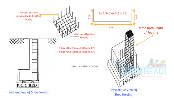
For the calculation of the total quantity of steel required for the Plain footing, we are adopting these dimensions for bars.
Adopted:-
- Mesh extended till Depth of Footing is adopted for F5 footings
- Dimensions of Footing are 0.6×0.6×0.4 (Length × Breadth × Depth)
- Dia of X Bars is 16mm (Dia 16mm@80mm C/C)
- Dia of Y Bars is 16mm (Dia 16mm@80mm C/C)
- which means Center to center spacing between X bars & Y bars is 80mm
Remember Proper Concrete cover should be adopted for the reinforcement in Footings to resist it from corrosion.
Concrete Cover deduction:
As per condition, concrete cover of 0.1m is deducted from all sides of mesh. In Mesh extended till Depth of Footing, extra bar is bent towards the depth.
| Length of Each X bar | = 0.4+0.3+0.3 = 1.0m |
| Length of Each Y bar | = 0.4+0.3+0.3 = 1.0m |
| No. of X bars | [(Y Bar Length)/Spacing]+1 = [0.4/0.08]+1 =~6bars (Don’t include extra bar length in calculating no. of bars) |
| No. of Y bars | [(X Bar Length)/Spacing]+1 = [0.4/0.08]+1 = ~6bars |
| Total Length of X bars | = Length of each X bar × No. of X Bars = 1.0 × 6 =6m |
| Total Length of Y bars | = Length of each Y bar × No. of Y Bars = 1.0 × 6 =6m |
| Total No. of ’12m’ X bars | = 6/12 = 0.5bars |
| Total No. of ’12m’ Y bars | = 6./12 = 0.5bars |
| Weight of steel required for 1m of 16mm bar | = D2/162 = 162/162 = 1.58kg/m |
| Total weight of steel required for X bars | = 1.58 × 6 = 9.48Kgs |
| Weight of steel required for 1m of 12mm bar | = D2/162 = 122/162 = 1.58kg/m |
| Total weight of steel required for Y bars | = 1.58 × 6 = 9.48Kgs |
Total Weight of Mesh extended till Depth of Footing
= Weight of steel required for X bars + Weight of steel required for Y bars
=9.48Kgs+9.48Kgs =18.96Kgs
Combined Footing Bar Bending Schedule:-
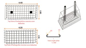
For the calculation of the total quantity of steel required for the combined footing, we are adopting these dimensions for bars.
Adopted:-
- Hook Mesh is usually adopted for F5 footing.
- Dimensions of Footing are 4.2×1.7×0.9(Length × Breadth × Depth)
- Dia of X Bars is 12mm (Dia 12mm@100mm C/C)
- Dia of Y Bars is 12mm (Dia 12mm@100mm C/C)
- which means Center to center spacing between X bars & Y bars is 100mm
Remember Proper Concrete cover should be adopted for the reinforcement in Footings to resist it from corrosion.
Concrete Cover deduction:
As per condition, concrete cover of 0.1m is deducted from all sides of mesh. In Mesh extended till Depth of Footing, extra bar is bent towards the depth.
| Length of Each X bar | = 4.2+2×9d d = 12mm = 0.012m = 4+2×9×0.012 = 4.41m |
| Length of Each Y bar | = 1.7+2×9d d = 12mm = 0.012m = 1.7+2×9×0.012 = 1.91m |
| No. of X bars | [(Y Bar Length)/Spacing]+1 = [1.7/0.1]+1 =18bars (Don’t include hook length in calculating no. of bars) |
| No. of Y bars | [(X Bar Length)/Spacing]+1 = [4.2/0.1]+1 = 43bars |
| Total Length of X bars | = Length of each X bar × No. of X Bars = 4.41 × 18 =79.38m |
| Total Length of Y bars | = Length of each Y bar × No. of Y Bars = 1.91 × 43 =82.13m |
| Total No. of ’12m’ X bars | = 79.38/12 = 6.6bars |
| Total No. of ’12m’ Y bars | = 82.13/12 = 6.84bars |
| Weight of steel required for 1m of 16mm bar | =D2/162 =122/162 =0.88kg/m |
| Total weight of steel required for X bars | = 0.88 × 79.38 = 69.85Kgs |
| Weight of steel required for 1m of 12mm bar | =D2/162 =122/162 =0.88kg/m |
| Total weight of steel required for Y bars | = 0.88 ×82.13 = 72.27Kgs |
Total Weight of Hook Mesh
= Weight of steel required for X bars + Weight of steel required for Y bars
= 69.85Kgs+72.27Kgs =142.12Kgs
Abstract of above calculation:-
Total Weight of steel required for above plan
= Total weight of steel required for X bars +Total weight of steel required for Y bars
= 150.88Kgs+130.88Kgs =281.76Kgs = 0.28Ton
- Bar Bending Schedule Basics
- How to calculate Cutting length of stirrups in Beams and Columns
- Bar Bending schedule of Tie beams / Strap Beams
- Bar Bending schedule of Neck column
- Bar Bending schedule of Floor column
- Bar Bending schedule of Slabs
- Bar Bending schedule of Doglegged staircase
- Difference between Lap Length and Development Length
- What is Bond, Bond stress, Anchorage length & bond, Development
Don’t Forget to Share With your friends! Sharing is Caring:)
For Instant updates Join our Whatsapp Broadcast. Save our Whatsapp contact +9700078271 as Civilread and Send us a message “JOIN”


Well done bro keep going
Thanks for ur inputs
Good job brother, It’s really super
Good job Krishna ji it’s very helpful
well done..you made my day…Thanks..hoping to see upcoming detail estimation of slab and beam reinforcement
dimension of footing is 1.5×1.5×0.9, but used 1 instead of 1.5,can you pls explain…anyway I appreciate your work.
Excellent….
Excellent infformation. Thanks a lots
Excellent information a lot of tnx,I learn a lot of knowledge
Very nice contribution to civil construction.
Thanks For Wonderfull Information , keep giving Ideas of Footing and About Pile foundation Details , Can help a lot, Ravichandran p
I heartily Thanks for your sir for very good information
thanks for ur words! Join our dedicated civil engineers forum let help each other
link: forum.civilread.com
I lyk dis site.. Add more
thank you dear for your all information’s stay blessed
Hiii actually I want to know that which size of steel bar is used for footing purpose for g+4
it depends on design usually we use 10mm-12mm
Hi Krishna, u’re doing a great job here, keep it up. Please I will like to know the design code or a textbook to consult to get info such as the hook length for footing(9D), weight of 1m steel(D2/162) to reinforced my conviction about what I read here. Thanks
Good job ji it’s very helpful
i dnt know english pls send in telugu
use google translate 🙂
Thanks for informing
How to process calculation bar quantity any pile or mat foundation.
go through the article clearly
plane footing cutting length and depth ofstepped footing is wrong pls try to correct it
All values mentioned are for understanding the concept and these values cant be used for design purpose.
very Nice Information Thanks Buddy
why r u taking +1 in no of bars in x and y calculation
its a formula
There is have any deductions in a calculation of cutting length for rebars in any structural units like slabs ,beams columns and footings …if there is any deductions please explain .
the deductions and the complete design of slabs, beams , columns are explained clearly here
https://civilread.com/tag/bar-bending-schedule
can u plz add combined footing
plese vartical ka steel cutting length bhi explane kro
i’m looking for combined isolated footing. Where is it ?
soon u can see it in site
nice very helpful but you miss footing with top mesh and bottom mesh. i want a bbs of water tank please upload it .and isolated footing too. thanks for sharing for free
Good job brother, ur thinking of sharing ur subject really super
any software for this
generally which diameter of steel used in slab column footing beam?
it depends for residential 12-16mm bars
I want estimation calculation for trapezoidal footing for residential building (g+1)
I want to know how to design eccentric footing (F5 in this topic)?
kudos ! Great job